
Workflow Structure
Before we describe the actual Data Patterns in detail, we first present a standard set of definitions for the various components of a workflow system that we will utilise throughout this body of work. A workflow or workflow model is a description of a business process in sufficient detail that it is able to be directly executed by a workflow management system. A workflow model is composed of a number of tasks which are connected in the form of a directed graph. An executing instance of a workflow model is called a case or process instance. There may be multiple cases of a particular workflow model running simultaneously, however each of these is assumed to have an independent existence and they typically execute without reference to each other.
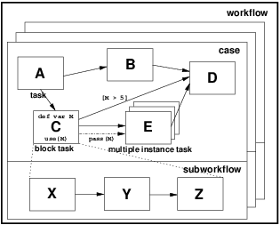
Figure 1: Components of a workflow
There is usually a unique first task and a unique final task in a workflow. These are the tasks that are first to run and last to run in a given workflow case. Each invocation of a task is termed a task instance. A task instance may initiate one or several task instances when it completes. This is illustrated by an arrow from the completing task to the task being initiated e.g. in Figure 1, task instance B is initiated when task instance A completes. This may also occur conditionally and where this is the case, the edge between task instances indicates the condition that must be satisfied for the subsequent task instance to be started e.g. task instance D is initiated when task instance C completes if the data element M is greater than 5.
A task corresponds to a single unit of work. Four distinct types of task are denoted: atomic, block, multi-instance and multi-instance block. We use the generic term components of a workflow to refer to all of the tasks that comprise a given workflow model. An atomic task is one which has a simple, self-contained definition (i.e. one that is not described in terms of other workflow tasks) and only one instance of the task executes when it is initiated. A block task is a complex action which has its implementation described in terms of a sub-workflow. When a block task is started, it passes control to the first task(s) in its corresponding sub-workflow. This sub-workflow executes to completion and at its conclusion, it passes control back to the block task . E.g. block task C is defined in terms of the sub-workflow comprising tasks, X, Y and Z.
A multiple-instance task is a task that may have multiple distinct execution instances running concurrently within the same workflow case. Each of these instances executes independently. Only when a nominated number of these instances have completed is the task following the multiple instance task initiated. A multi-instance block task is a combination of the two previous constructs and denotes a task that may have multiple distinct execution instances each of which is block structured in nature (i.e. has a corresponding sub-workflow). The control flow between tasks occurs via the control channel which is indicated by a solid arrow between tasks. There may also be a distinct data channel between workflow tasks which provides a means of communicating data elements between two connected tasks. Where a distinct data channel is intended between tasks, it is illustrated with a broken (dash-dot) line between them as illustrated in Figure 1 between task instances C and E. In other scenarios, the control and data channels are combined, however in both cases, where data elements are passed along a channel between tasks, this is illustrated by the pass() relation, e.g. in Figure 1 data element M is passed from task instance C to E. The definition of data elements within the workflow is illustrated by the def var variable-name phrase. Depending on where this appears, the variable may have task, block, case or workflow scope indicating the level at which the data element is bound. The places where a given data element can be accessed are illustrated by the use() phrase. In the case of workflow, case and block level data elements, these may be passed between tasks by reference (i.e. the location rather than the value of the data element is passed). This is indicated through the use of the & symbol e.g. the pass(&M) phrase indicates that the data element M is being passed by reference rather than value.
The Patterns presented in this body of work are intended to be language independent and do not assume a concrete syntax. In the absence of an agreed workflow model, the aim is to define them in a form that ensures they are applicable to the broadest possible range of workflow systems. As such, we use informal diagrams throughout this paper for illustrating workflow execution instances. The aim of these diagrams is to illustrate the scope of workflow data and the manner in which it is passed between various workflow components. They do not have a formal semantics for the control perspective. Where this is required, we use the YAWL notation [ AH05] which provides a more rigorous means of describing workflow control structures.